Power Rail Probe: An Open Hardware Tool for Millivolt Ripple Measurements
Low-noise oscilloscope power rail probe
At a glance
- What is it?
- This review examines the blinken/power-rail-probe, an open hardware oscilloscope probe that applies a DC offset to measure millivolt-level ripple on rails up to 20V. The design offers a low-cost alternative to commercial probes, with specific trade-offs in bandwidth, noise, and usability.
- Who is it for?
- Adopt this probe if you are a hardware engineer or hobbyist who needs to measure millivolt-level ripple on rails up to 20V and wants an open, low-cost alternative to commercial probes like the Tektronix TPR1000. Avoid it if you require calibrated absolute measurements or need to probe rails above 20V without external attenuation.
- Can I use it commercially?
- Check first. The repository uses a licence we do not classify automatically, so read its LICENSE file before any commercial use.
- Is it still maintained?
- Activity is slowing. The repository last received commits 9 months ago.
- What is it written in?
- Mainly Shell, according to GitHub's language statistics.
Answers come from the project's GitHub data, last synced on October 22, 2026, and from our analysis. They are not legal advice.
Star history
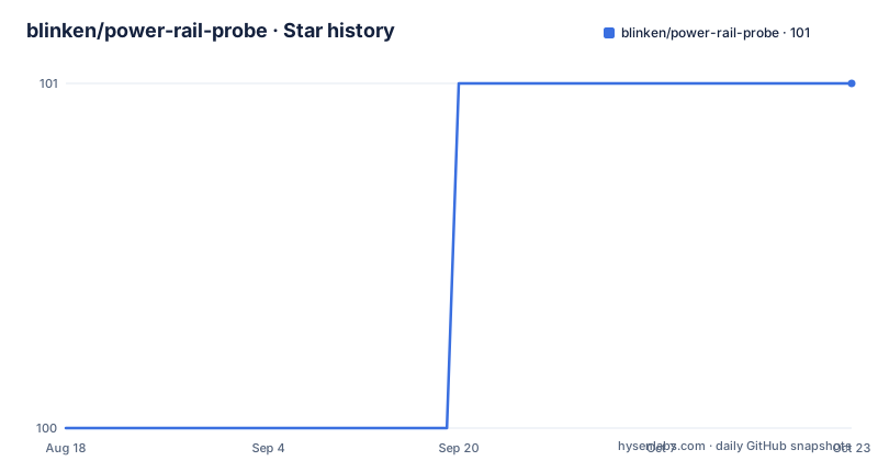
- blinken/power-rail-probe101 ★ · +1
| Repository | 2026-08-18 | 2026-10-22 |
|---|---|---|
| blinken/power-rail-probe | 100 | 101 |
1 Stars in the last 65 days, measured from the daily GitHub snapshot. Compare with other projects
Editorial analysis
What Problem This Solves and Who It Is For
Oscilloscopes have a fundamental limitation when measuring power rail ripple: the DC component of a 5V or 12V rail sits far above the millivolt-level AC noise you want to see. Setting the vertical scale to 5V per division to accommodate the rail makes a 10mV ripple invisible. This probe solves that by applying a fixed DC offset, so the oscilloscope sees 0V DC and can be set to 1mV per division. The README states it is "effectively a much more powerful DC offset function for your oscilloscope." The target user is anyone debugging power integrity: embedded engineers, board designers, or electronics hobbyists who need to see ripple and transients on a rail without buying a dedicated active probe. The design is open hardware, with Gerber files and a BOM released under CC BY-SA 4.0, so it also appeals to makers who want to build or modify their own test equipment.
How the Probe Works: Offset, Attenuation, and Isolation
The probe sits between the power rail and the oscilloscope. It passes AC while applying a fixed, adjustable DC offset. The offset is set with a high-precision 5-turn potentiometer, which the README identifies as a Nidec M-1305. The oscilloscope then sees 0V DC, allowing ripple to be viewed at high sensitivity. The probe has an input impedance of 50kΩ from 0 to 30kHz, dropping to 50Ω from 30kHz to 1GHz. That dual impedance is a key design choice: it preserves low-frequency accuracy while matching the 50-ohm termination common on RF-capable scopes. The signal is attenuated by a factor of 1:1.2, or about -0.9dB, which the README notes as an average value with ±1dB variation. The probe is battery powered, using two 18650 Li-Ion cells, to minimize noise from ground loops and mains coupling. It also provides isolation between the chassis/USB and the BNC connectors, which prevents ground loops that would otherwise corrupt millivolt-level measurements. An over-range indicator lights up when the input signal exceeds the offset setting, which is a practical feature for avoiding clipping.
Getting It Running: Commands, Config, and Physical Setup
This is not software you install; it is hardware you assemble or buy. The README points to a fully assembled unit for approximately £249 from paradar.co.uk, or you can buy blank PCBs, enclosures, and front panels to build it yourself. The repository contains the KiCad schematic and PCB layout files, plus a BOM CSV. To use the probe, you connect it directly to the power rail, either with a 1X oscilloscope probe or a direct cable connection. The README specifies that the probe should be connected to an oscilloscope set to 50-ohm input impedance, and it works best with signal source impedances below 1 ohm. That last point is critical: if your rail has higher impedance, the probe's loading will affect the measurement. The batteries are recharged via USB-C (requiring a 9V+ USB-PD supply) or a DC barrel jack, and charging only happens when the instrument is off. There are no software commands or configuration keys; the only 'config' is the potentiometer adjustment for the offset.
Performance Specifications and Their Limits
The README lists specific performance numbers for v1.0.1. Maximum voltage offset is ±20V, which limits the rail voltage you can probe directly. The frequency response is flat within 1dB from approximately 3MHz to 490MHz, and within 2.5dB from 150kHz to 550MHz. That means it is not designed for low-frequency ripple below 150kHz; the response degrades there. Noise is specified as less than 500µV peak-to-peak over the full bandwidth, but the simulated noise analysis gives more detail. The total noise introduced over 10Hz to 1GHz is 78.7µVrms, which translates to 472.2µVp-p at 6σ. That is a worst-case upper limit; for a narrower bandwidth like 10kHz to 20kHz, the noise drops to 12.9µVrms. These numbers come from SPICE simulation, not from measured data in the README, so treat them as design targets. The v1.0 version has a 3.7dB dip at approximately 1.2MHz, which v1.0.1 fixes. The v1.1 version, still in simulation, claims flatness within 0.5dB to 1GHz, but that is unverified.
A Genuine Limitation: The 50-Ohm Input Impedance Trade-off
The probe's input impedance is 50Ω above 30kHz, which is a serious limitation for many power rail measurements. Most power rails are low impedance, often well below 1 ohm, so the probe's 50Ω load does not significantly affect the rail. But if you are probing a rail through a long cable or a high-impedance node, the 50Ω termination will load the circuit and change the measurement. The README explicitly says it works best with inputs below 1-ohm impedance, so this is a known constraint. Another limitation is the ±20V offset range. If you need to measure a 24V rail or a negative rail below -20V, this probe will not work without external attenuation, which would add noise and defeat the purpose. The battery power is a plus for noise, but it also means you must remember to recharge the 18650 cells, and charging requires a specific USB-PD supply, which adds a hidden cost if you do not already own one. Finally, the probe is not calibrated; the attenuation is given as an average with ±1dB variation, so for precise absolute measurements you would need to characterize your specific unit.
Alternative: The Tektronix TPR1000 and the Cost Difference
The README explicitly compares this probe to the Tektronix TPR1000, a commercial active power rail probe. The TPR1000 is a mature, calibrated instrument with a specified bandwidth and a known price, typically in the thousands of dollars. The open hardware probe costs less than 10% of that price, according to the README. The difference in approach is fundamental: the TPR1000 uses active electronics to buffer and offset the signal, offering a flat response and a specified noise floor, but it requires a dedicated power supply and is closed hardware. The blinken probe uses a passive network with an adjustable offset, relying on the oscilloscope's 50-ohm input for termination. That simplicity is why it can be sold for £249, but it also means you get less predictable performance. The TPR1000 has a specified bandwidth and calibrated attenuation; this probe gives you an average attenuation with ±1dB variation. If you need repeatable, documented measurements for certification or production testing, the TPR1000 is the safer choice. If you are prototyping or troubleshooting and can accept some uncertainty, the open probe is a viable budget option.
Maintenance, License, and Upgrade Considerations
The project is licensed under CC BY-SA 4.0 for the hardware files, which means you can use, modify, and distribute the design as long as you share your modifications under the same license. That is a real advantage for a hardware project: you can adapt the probe to your needs, but you must share your changes. The repository is not archived, and the last push was in December 2023, with a v1.0 release at that time. The README mentions v1.0.1 as the current characterized version and v1.1 as simulation-only. There are no release notes beyond the initial v1.0, so the maintenance cadence is unclear. The hardware itself has a maintenance cost: batteries need periodic replacement, and the 5-turn potentiometer may wear out with heavy use. The BOM includes specific parts like the LMP7731 opamp and ADP7142 LDO, which are standard components, but sourcing them may vary. If you build it yourself, you take on the risk of assembly errors and the need to verify performance against the simulated noise figures. The project appears to be a one-person effort, so support is limited to GitHub issues. Before adopting, verify that the version you want has been characterized and that you can source the parts or buy a pre-assembled unit.
Editorial conclusion
Adopt this probe if you are a hardware engineer or hobbyist who needs to measure millivolt-level ripple on rails up to 20V and wants an open, low-cost alternative to commercial probes like the Tektronix TPR1000. Avoid it if you require calibrated absolute measurements or need to probe rails above 20V without external attenuation. Before adopting, verify the specific version you plan to use: v1.0.1 is the only fully characterized and purchasable version; v1.1 remains simulation-only, so its real-world performance is unconfirmed. Also check that your oscilloscope supports 50-ohm input impedance, as the probe expects that termination.
Frequently asked questions
What is a power rail probe?
It is a probe that lets an ordinary oscilloscope see millivolt-level ripple on a supply. This one works by passing the AC component of the rail and applying an adjustable, then fixed, offset to the DC level, so the scope sees 0V DC and the ripple can be viewed at 1 mV per division instead of 5 V per division.
What is a power rail?
In this project's terms it is a supply rail that the probe connects to directly, up to 20V, either through a 1X oscilloscope probe or a plain cable. The worked example measures 60mV peak-to-peak ripple on a 20V rail, meaning the supply moves between 19.97V and 20.03V.
What does a power probe do?
Its stated purpose is to make ripple and transients visible on a rail whose DC level is far larger than the signal you care about. By subtracting a fixed offset, the probe puts the signal at the bottom of the scope's vertical range and, because the offset is adjustable and then held, it also lets DC sag and drift be examined.
What is the purpose of an oscilloscope probe in this design?
It is the connection method as much as the measuring tool. The rail can be reached through a 1X oscilloscope probe or a direct cable, and the probe then hands a zero-volt DC signal with the ripple on top to a scope set to 50 ohm input impedance, which is the setting the documentation requires and says works best below 1 ohm.
Official sources
Add this badge to your README
If you maintain this project, the badge below links readers to this analysis and shows its maintenance status from the daily GitHub snapshot. Paste the markdown into your README; add ?metric=license or ?metric=stars to the image URL for a different field.

[](https://hysenlabs.com/projects/blinken-power-rail-probe)Star history chart for your README
[](https://hysenlabs.com/projects/blinken-power-rail-probe)