PSLab Pico Firmware: USB CDC Instruments and Bus Gateways
PSLab Mini Firmware https://pslab.io
At a glance
- What is it?
- PSLab Pico Firmware is C firmware for a Raspberry Pi Pico-based PSLab that exposes logic analyser, oscilloscope, test signal, UART, and I2C controls through SCPI over USB CDC. It is aimed at instrument and embedded-protocol work, but the repository remains an incomplete port with no documented build command or GitHub release.
- Who is it for?
- Adopt this repository if you are developing firmware for a Raspberry Pi Pico-based PSLab and need its USB CDC SCPI architecture or bus gateway commands. Do not treat it as a ready-made instrument image yet: the README says the port is being prepared, gives no build tutorial, and labels the oscilloscope implementation rudimentary.
- Can I use it commercially?
- Check first. The repository uses a licence we do not classify automatically, so read its LICENSE file before any commercial use.
- Is it still maintained?
- Yes. The repository last received commits 55 days ago.
- What is it written in?
- Mainly C, according to GitHub's language statistics.
Answers come from the project's GitHub data, last synced on November 7, 2026, and from our analysis. They are not legal advice.
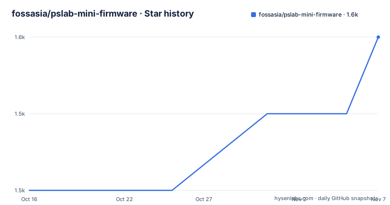
Star history
- fossasia/pslab-mini-firmware1,550 ★ · +2
| Repository | 2026-10-16 | 2026-11-07 |
|---|---|---|
| fossasia/pslab-mini-firmware | 1.5k | 1.6k |
2 Stars in the last 22 days, measured from the daily GitHub snapshot. Compare with other projects
Editorial analysis
PSLab Pico's USB CDC Instrument Surface
This firmware targets a specific job: exposing a Raspberry Pi Pico-based PSLab to a host as a controllable electronics instrument. The host can configure and operate a logic analyser, read oscilloscope captures, generate a square test signal, and communicate with external devices through UART or I2C. The repository is not a general-purpose operating-system image. Its application layer is built around SCPI commands received through a USB CDC serial endpoint.
That interface makes the firmware relevant to embedded developers who want to integrate an instrument into an automated measurement setup. PulseView support is documented through the out-of-tree `tools/sigrok/pslab-pico` hardware driver, which uses the USB CDC SCPI interface and converts logic analyser binary blocks into samples that sigrok decoders can interpret. The README names UART, I2C, and SPI as examples of digital buses that PulseView's normal decoders can handle after capture.
The repository is a port in progress, however. The opening README statement says it "is being prepared for the Raspberry Pi Pico based PSLab firmware port." This status matters more than the breadth of its command list. The code exposes several instrument paths, but the README does not claim that the entire port is finished or production-ready.
Startup, Transport, and SCPI Data Flow
The documented startup sequence separates hardware services from protocol processing. `SYSTEM_init()` runs first and initializes the platform layer, utility logging, UART-backed standard output and error syscalls, the status LED, test signal generation, and USB CDC. Only after that does the protocol layer create its SCPI context and begin command processing. This division keeps peripheral initialization separate from command dispatch.
USB CDC is reserved for SCPI commands and binary instrument data. Standard output and standard error from Newlib are redirected to the hardware UART transport instead. `src/system/bus/uart.c` retains a hardware-independent bus layer, while `src/platform/uart_ll.c` supplies the Pico-specific low-level implementation using RP2040 or RP2350 UART interrupts. `LOG_task` drains pending internal log entries. This means a host using USB CDC for SCPI should not expect all firmware diagnostics on that same endpoint.
Protocol state is centered in `src/application/protocol/common.c`, with separate handlers for the logic analyser and oscilloscope. The embedded parser is `lib/scpi-parser-2.3`. SCPI parser errors enter the command error queue reported by `SYST:ERR?`; internal logs take the UART-backed output path. Keeping those channels separate simplifies host parsing, but it also means debugging must account for a physical UART logging connection when USB CDC appears quiet.
Logic Analyser and RP2350 ADC Capture Paths
The logic analyser path combines SCPI configuration, USB CDC binary transfer, and PIO/DMA capture. Commands such as `LA:CONF:PINS`, `LA:CONF:DIV`, and `LA:CONF:SAMPLES` define the capture. `LA:TRIG:MODE`, `LA:TRIG:PIN`, and `LA:TRIG:LEVEL` select trigger behavior. Acquisition is started with `LA:CAPT`, data can be read through `LA:DATA?`, or a stream can be controlled with `LA:STREAM:START` and `LA:STREAM:STOP`.
The oscilloscope follows a different route. `src/platform/adc_capture.c` captures samples through the Pico internal ADC, and `src/system/instrument/dso.c` exposes a rudimentary oscilloscope instrument. It supports only one channel at a time. Channels `0` through `3` map to `GPIO26` through `GPIO29`, and each sample is a little-endian 12-bit ADC value stored in a `uint16_t` word.
The documented oscilloscope defaults are channel `0` on `GPIO26`, a sample rate of `100000` samples per second, `1024` samples, trigger mode `OFF`, trigger level `2048`, and trigger slope `RISE`. Configuration and binary retrieval are available through `DSO:CONF:CHAN`, `DSO:CONF:RATE`, `DSO:CONF:SAMP`, the trigger commands, and `DSO:READ?`. These are concrete defaults, not claims about achieved resolution or signal fidelity. The README documents the ADC width and rate, but does not state accuracy, noise, bandwidth, or usable sample-rate limits.
UART and I2C Gateways over SCPI
The firmware can act as a bus master for external serial sensors and peripherals. Its initial UART gateway exposes UART1 through SCPI while reserving UART0 for logging. UART1 uses `GPIO4` for TX, `GPIO5` for RX, and 8N1 format. The command group covers bus selection, baud rate, timeout, opening and closing the port, binary writes, reads, availability checks, clearing, flushing, and combined transactions.
Binary UART payloads use SCPI arbitrary blocks. The README states that `WRITe`, `READ?`, and `TRANsact?` therefore carry binary data safely. It also places a hard limit of 512 bytes on each transfer. That boundary affects automation design: a larger sensor response must be split across reads rather than treated as one unrestricted gateway transaction.
The I2C gateway uses the Pico I2C controllers in 7-bit master mode. I2C0 defaults to `GPIO0` for SDA and `GPIO1` for SCL at 100 kHz. I2C1 is mapped to `GPIO6` for SDA and `GPIO7` for SCL. `BUS:I2C:CONFigure:BUS` selects controller 0 or 1, while `BUS:I2C:CONFigure:RATE` changes the configured rate.
Building the First PSLab Pico Firmware Use
The repository contains a root `CMakeLists.txt`, `pico_sdk_import.cmake`, and a minimal entrypoint at `src/application/main.c`. Those entries establish a Pico SDK-based build layout. The README does not provide installation steps, a required SDK version, subdirectory initialization commands, build directory names, environment variables, or the command used to produce a flashable image. As a result, a reproducible first build cannot be transcribed from this repository documentation.
The first documented interaction would be to connect the programmed Pico over USB CDC and query the instrument identity with the following SCPI command. The reader should receive an identity response from the firmware, but the README does not show its format or documented response text.
*IDN?After identity succeeds, the host can query the logic analyser's current rate or metadata before configuring a capture. The README lists these queries but does not specify a host-side terminal configuration.
LA:CONF:RATE?
LA:METADATA?
For a square test signal, configure its pin and frequency, then start generation. The README does not document the resulting waveform's amplitude, duty cycle, timing accuracy, or pin conflicts, so the command sequence should not be treated as a full electrical specification.
TEST:SQUARE:CONF <gpio> <frequency_hz>
TEST:SQUARE:START
The host should also check `SYST:ERR?` after invalid or rejected SCPI input. That query reports parser and protocol errors from the SCPI error queue, not internal logging output.
Porting Constraints, Licensing, and Upgrade Boundaries
The clearest constraint is the unfinished port itself. The Pico test layout has not yet been added, according to the README, although existing host-side tests under `tests/` are retained. That separation limits confidence in the current firmware build and test workflow. There are no GitHub releases, so the repository does not offer a release history through that channel or identify a downloadable firmware artifact.
The oscillator has narrower hardware scope than a multi-channel instrument. It uses the RP2350 internal ADC, supports one channel at a time, and exposes four GPIO mappings. Internal ADC characteristics may also constrain what the interface can measure, but this README does not document those electrical characteristics, so specific performance conclusions would be unsupported.
The project uses `lib/CException-1.3.4` and an embedded `lib/scpi-parser-2.3`. Vendored dependencies reduce integration ambiguity because they live in the repository tree, but updates still require reviewing the corresponding library changes and the retained STM32-oriented utility code. The license is marked as custom because GitHub cannot classify it. The available description does not summarize redistribution, modification, attribution, or commercial-use terms, so those conditions must be checked directly in `LICENSE.md`.
The last push was on 2026-09-13. That date is recent, but it does not by itself establish release readiness. Adopters need to inspect the active `dev26` branch because it is the documented default branch, rather than assuming a tagged or packaged firmware exists.
Editorial conclusion
Adopt this repository if you are developing firmware for a Raspberry Pi Pico-based PSLab and need its USB CDC SCPI architecture or bus gateway commands. Do not treat it as a ready-made instrument image yet: the README says the port is being prepared, gives no build tutorial, and labels the oscilloscope implementation rudimentary. Verify the custom LICENSE.md terms first, then confirm that the Pico SDK, hardware targets, unfinished Pico test layout, and exact peripheral behavior meet your requirements.
Frequently asked questions
Which interfaces does PSLab Pico Firmware expose to a host?
It exposes SCPI commands and binary instrument data through USB CDC. Internal firmware logging is routed to hardware UART instead.
Can PSLab Pico Firmware use I2C and UART peripherals?
Yes. The documented gateways expose UART1 and the Pico I2C controllers through SCPI, with binary UART transfers capped at 512 bytes.
Does the README provide a complete PSLab Pico firmware build and flash tutorial?
No. It identifies a root CMake build, Pico SDK discovery file, and firmware entrypoint, but supplies no SDK version, build command, or flash procedure.
Official sources
Add this badge to your README
If you maintain this project, the badge below links readers to this analysis and shows its maintenance status from the daily GitHub snapshot. Paste the markdown into your README; add ?metric=license or ?metric=stars to the image URL for a different field.

[](https://hysenlabs.com/projects/fossasia-pslab-mini-firmware)Star history chart for your README
[](https://hysenlabs.com/projects/fossasia-pslab-mini-firmware)Was this useful?